

A cylinder that is too small, poorly guided, incorrectly controlled, or starved of air will produce missed positions, unstable speeds, seal wear, and unplanned stoppages. By the end, you will be able to match the actuator, controls, air treatment, piping, and compressor capacity to the machine’s load and cycle instead of choosing components by bore, horsepower, or nominal pipe size alone.
Key takeaways
- Calculate bore size from force, pressure, and efficiency.
- Match stroke, rod diameter, and mounting to the real load path.
- Specify the cylinder, valve, flow controls, and sensors as one system.
- Plan peak simultaneous air demand before selecting the compressor and piping.
How a pneumatic cylinder creates controlled linear motion
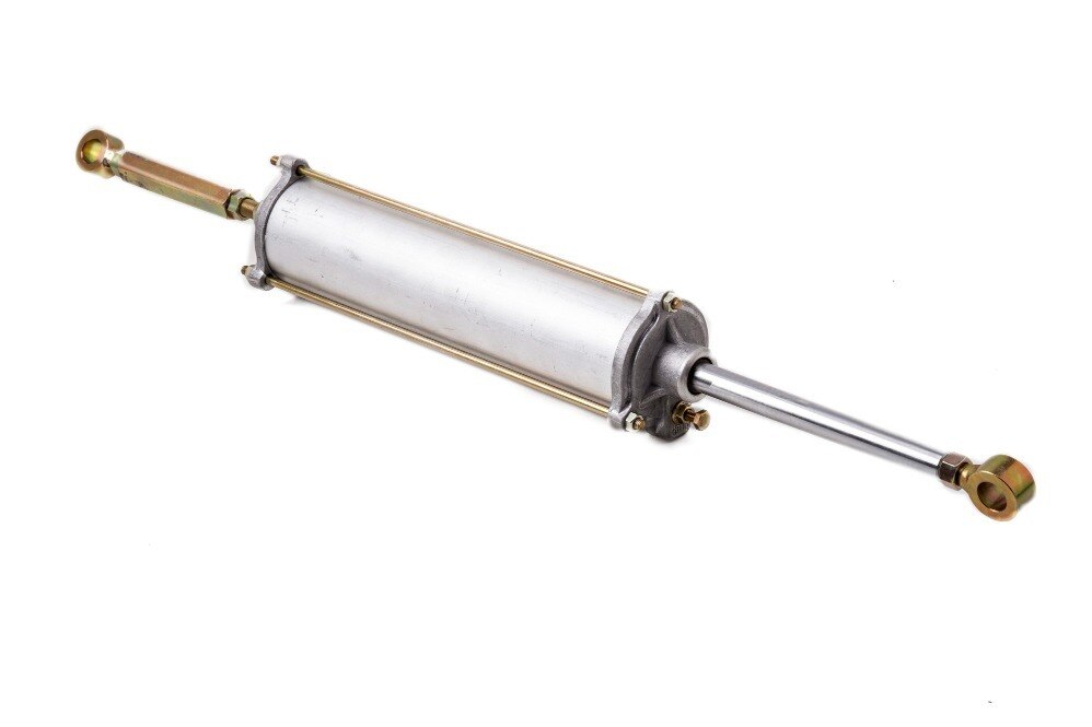
A pneumatic cylinder creates controlled linear motion by converting compressed-air pressure into piston force, then transmitting that force through a rod. During pneumatic cylinder operation, a directional valve sends air to one side of the piston for extension and the other for retraction.
Effective area matters: the rod reduces available retraction force, while friction, pressure loss, and acceleration reduce theoretical force.
Compare single-acting cylinder simplicity with double-acting cylinder air consumption and return force limitations before choosing.
| Architecture | Motion and space | When it fits | Main limitation |
|---|---|---|---|
| Single-acting cylinder | Air-powered stroke with spring return | Clamping, ejecting, or short strokes where the return load is predictable | Spring force reduces usable stroke force and return speed |
| Double-acting cylinder | Air-powered extension and retraction | Repeated positioning, pushing, pulling, and controlled reversal | Uses air on both strokes and needs a correctly sized valve and supply |
| ISO 15552 tie-rod | Robust standard cylinder with broad bore and mounting options | General factory automation and higher loads | Requires more installation space |
| ISO 6432 round | Slim stainless or aluminium body | Light-duty, compact mechanisms | Limited bore, stroke, and side-load tolerance |
| ISO 21287 compact | Short body for a given stroke | Tight machine layouts | Less room for cushioning and mounting |
| Rodless or guided | Travel without a projecting rod, or integrated load guidance | Long travel or payloads needing guidance | Higher alignment and contamination demands |
Treat the cylinder as an actuator, not a guide. Use external rails, a guided cylinder, or a floating rod-end coupling when tooling creates side load; otherwise rod bending and seal wear can destroy reliability.
Select bore, stroke, rod, and mounting from the real load
Size the cylinder from the worst real load, not catalogue thrust. Choose the cylinder bore diameter from the required force at the lowest operating pressure, then allow for seal friction, pressure losses, and acceleration.
Use the extension force and retraction force calculation F=pA and F=p(A−rod area). At 6 bar gauge, a 100 mm bore produces about 4.71 kN theoretical extension force; with a 25 mm rod, retraction force falls to about 4.42 kN. Keep a practical force margin after these losses.
- Set the stroke length from the machine’s actual travel, including clearance at both ends. A longer unsupported stroke increases rod bending and buckling risk.
- Select rod diameter from the push load, unsupported length, end-mounting condition, and load eccentricity. Check the manufacturer’s buckling chart; a simple thrust margin cannot prove a slender rod is safe.
- Match the mount to the motion geometry. Clevis, trunnion, or spherical mounts accommodate angular movement, while a rigid flange and misaligned load can drive side load into the rod and guide seals.
- Size speed from valve flow, tubing length and bore, fittings, exhaust restrictions, load, and cushion adjustment. Pressure alone does not set speed, and a restricted exhaust commonly makes retraction slow or erratic.
Confirm that the rod can resist the load at the worst position, not just at mid-stroke. A piston magnet sensor proves the piston passed its switch; it does not prove the rod reached position or transferred the payload. Critical operations need independent position, pressure, or workpiece-presence verification.
Choose the actuator and valve package as one motion system
Choose the actuator from the motion envelope, then size the directional valve, flow controls, sensors, and end cushioning to match its cycle. A valve with inadequate exhaust flow can make retraction slow and inconsistent even when supply pressure is correct.
| Actuator option | Directional valve and flow control | Sensing and cushioning |
|---|---|---|
| ISO 15552 tie-rod cylinder | 5/2 valve for double acting; meter-out controls at both ports | Reed or solid-state switches; adjustable built-in cushions |
| ISO 6432 round cylinder | 5/2 valve for repetitive two-way motion; meter-out controls | Magnetic switches; adjustable cushions where fitted |
| ISO 21287 compact cylinder | 5/2 valve with short tubing and sufficient exhaust capacity | Compact magnetic sensors; built-in cushioning for moderate speeds |
| Rodless cylinder | 5/3 centre-closed valve when holding position matters; meter-out controls | Position sensors; external shock absorbers for high kinetic energy |
| Guided cylinder | 5/2 valve; use flow controls to prevent guide shock | End-position sensors; cushions matched to the guided load |
| Rotary actuator or custom design | Select the valve by required torque, angle, and flow; throttle exhaust | Angle sensors or switches; external damping when stops are abrupt |
Use a 5/3 valve with a centre-exhaust or centre-closed configuration only when its centre function suits the load; removing the signal does not mechanically support a suspended mass. Protect gravity-loaded motion with a brake, rod lock, counterbalance, or mechanical support.
Built-in cushions reduce end-of-stroke impact, but high speed or heavy tooling may require hydraulic shock absorbers or profile-controlled valves. Set sensors after final stroke adjustment, and verify that the valve, tubing, fittings, and exhaust silencer pass the required flow.
Prevent failures through air quality, commissioning, and safe isolation
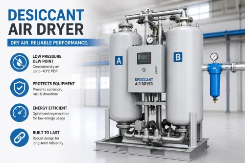
Most pneumatic failures begin with contaminated air or debris introduced during installation. Specify ISO 8573-1 air quality by particle, water, and oil classes; do not accept “clean, dry air” as a specification. Use a filter regulator lubricator only when the cylinder and valve manufacturer requires oil.
Adding a lubricator to a non-lubricated system can shorten seal life after oil is removed.
Commission new or modified pipework before connecting the actuator:
- Cut tubing squarely, deburr the end, and remove swarf.
- Keep thread sealant out of the bore and valve passages.
- Flush the lines until no scale, water, or sealant emerges.
- Check fittings and tubing for leaks at operating pressure.
Set flow controls and adjustable cushions while observing the real load, not an unloaded cylinder. Excessive cushioning slows the final stroke; insufficient cushioning creates impact, vibration, and mount damage. Inspect exhaust silencer maintenance points because oil saturation or blockage raises backpressure and can mimic a cylinder fault.
A reed switch proximity sensor has limitations: it detects the magnet through a defined sensing zone, but vibration, incorrect mounting, magnetic interference, and high switching frequency can cause missed signals. Confirm the sensor’s voltage, load, repeatability, and position during commissioning.
Follow ISO 4414 at system level. Isolate the supply, exhaust trapped air, verify zero pressure, and restrain gravity-driven or externally loaded motion before servicing; an exhaust valve cannot support a suspended load. Prevent unexpected restart with a lockable isolation method and a tested emergency-stop sequence.
Size the air supply for simultaneous peak demand
Size the compressor from every cylinder that moves together, not from the largest bore. For each stroke, calculate free-air consumption as swept volume × absolute cylinder pressure ÷ atmospheric pressure. Add extension volume using the full piston area and retraction volume using piston area minus rod area; then include port, tubing, cushion, and leakage allowances.
Collect these inputs for every actuator:
- Bore, rod diameter, and stroke
- Pressure at the valve, in bar absolute
- Extension and retraction events per cycle
- Cycles per minute and machine duty cycle
- Cylinders involved in each simultaneous motion
- Grippers, blow-offs, valves, and other pneumatic devices
Multiply each cylinder’s per-cycle volume by its event frequency, then sum overlapping motions for peak demand. Use the time-averaged total for compressor loading, but check the compressor’s free-air delivery at the required discharge pressure against peak demand, receiver recovery, leakage, and an engineering margin. Motor horsepower alone does not establish usable capacity.
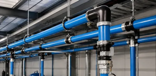
Select distribution pipe from peak branch flow, pipe length, fittings, and allowable pressure drop—not from the compressor outlet size. An undersized header can leave the compressor showing correct pressure while the far valve receives too little air during simultaneous motion.
SS Quality Air Solutions can check the calculated branch flow and pressure drop against the proposed aluminum pipe layout before installation. Use a receiver near rapidly cycling equipment when the header cannot supply short peaks without pressure collapse.
Frequently asked questions
How does a pneumatic cylinder create linear motion?
A directional valve sends compressed air to one side of the piston. Pressure produces piston force, and the rod transfers that force into extension or retraction.
How do you select a pneumatic cylinder for the load?
Use the real load, operating pressure, friction, duty cycle, mounting, stroke, and motion speed to select bore, rod diameter, and cylinder type.
Why should the actuator and valve be selected together?
The valve must provide enough flow for the target speed, while flow controls, sensors, tubing, and exhaust arrangements determine how smoothly the cylinder moves.
How can you prevent pneumatic cylinder failures?
Control water, oil, and particulate contamination; commission pressure and speed settings; inspect connections; and isolate and exhaust stored air before servicing.