

A compressed-air network loses efficiency when its pipe is undersized, its fittings add uncounted resistance, or condensate reaches tools and controls. You will be able to calculate a defensible pipe size, lay out a drainable distribution network, compare materials and fittings, and commission the installation without confusing pressure ratings with safe operating limits.
Key takeaways
- Size pipe for simultaneous peak flow at the farthest outlet.
- Use a sloped ring main with drains at low points.
- Match pipe, seals and fittings to pressure, temperature and air quality.
- Measure pressure at the tool inlet during peak demand.
Size the Pipe for Peak Flow, Not the Compressor Nameplate
Choose the pipe diameter from the flow required at the design pressure, not from the compressor’s nameplate horsepower or receiver size. Compressed air pipe sizing must preserve pressure at the most demanding outlet while several users operate simultaneously.
Document these design inputs before selecting a pipe diameter:
- Compressor output at the actual discharge pressure and control mode.
- Measured or engineered peak air demand, including simultaneous outlets and duty cycles.
- Straight-pipe length plus the equivalent length of elbows, tees, valves, filters, dryers and quick-connects.
- Allowable pressure loss from discharge to the point of use, with planned production expansion.
- Diversity assumptions, so you can revisit the calculation when shifts, tools or production lines change.
Keep total loss below roughly 10% of compressor discharge pressure; assign the piping only part of that budget because filters, dryers, regulators and hoses consume the rest. Intermittent blow-off, baghouse cleaning and large actuators can create local sag.
A receiver near that load can cover short peaks, but it cannot fix an undersized line during sustained flow.
| Sizing basis | Appropriate use | What goes wrong |
|---|---|---|
| Total nameplate consumption | Inventorying connected equipment | Oversizes the network when users do not run together |
| Simultaneous peak demand | Selecting the main and branches | Requires documented operating assumptions |
| Peak demand plus expansion | Planning future lines or shifts | Prevents later pressure loss from unplanned connections |
| Compressor output alone | Checking supply capacity | Does not prove adequate flow at the outlet |
Build a Ring Main That Controls Pressure Drop and Condensate
Build the ring main as a closed loop around the production area, giving each demand point two possible supply directions. This arrangement improves pressure stability and limits pressure drop compared with a single-ended header, where distant machines compete for flow through one route.
Specify these features in the compressed-air distribution layout:
- Slope the main line gently toward planned low points rather than allowing water to collect unpredictably.
- Take branch connections from the top of the main where practical, keeping bulk condensate below the outlet.
- Run each drop vertically downward, then connect the machine through a short upper return section so settled water does not flow directly into the tool.
- Fit condensate drain legs at low points, vertical drops, receiver outlets and before long rising sections.
- Place isolation valves at loop divisions and branch entries, allowing one section to be serviced without shutting the whole factory.
- Keep valves fully sized; an undersized valve can create more restriction than a long pipe.
Terminate each machine connection with a shutoff valve, filter, regulator and lubricator only when the equipment manufacturer specifies lubrication. Select filtration and drying for the required ISO 8573-1 class; pipe material alone does not establish air quality. Dirty filters and quick-connect couplings can erase the benefit of a well-sized header.
Do not rely on one compressor-room drain. Check every automatic drain for blockage and leakage: a failed-open drain continuously wastes compressed air, while a blocked drain sends condensate downstream. Use a manual isolation valve and service access at each drain.
Compare Pipe Materials and Check Every Fitting Joint
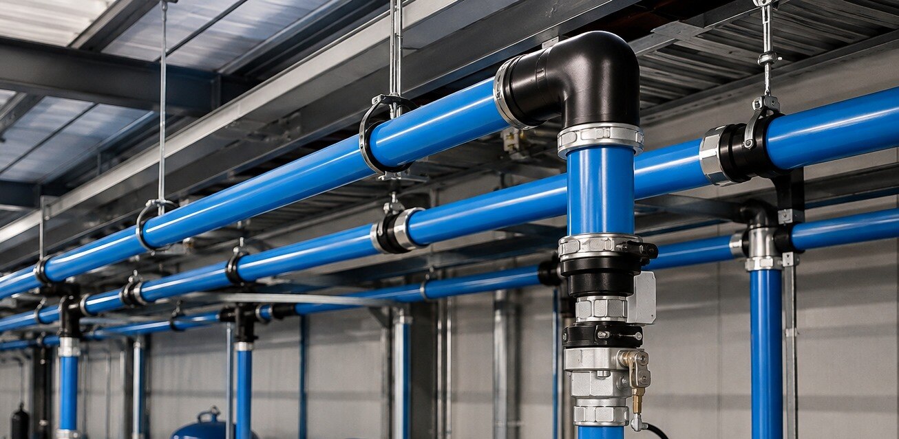
Choose the material by the plant’s failure conditions, not by purchase price alone. A clean, reconfigurable workshop favours aluminum compressed air pipe; a hot, chemically aggressive area may justify stainless steel pipe.
| Option | Corrosion and air path | Impact, modification and maintenance |
|---|---|---|
| Aluminum compressed air pipe | Smooth, corrosion-resistant bore reduces internal scale risk; verify pressure, temperature, fire and fitting compatibility | Light and quick to alter; protect exposed runs from vehicle impact and support every joint correctly |
| Black iron pipe | Internal rust and scale can contaminate air and increase pressure loss | Strong and familiar, but threading, welding, painting and later repairs consume time |
| Galvanized steel | Zinc coating delays rust, but zinc or scale can shed into the line | Handles abuse well; inspect cut threads and fittings where coating protection is damaged |
| Stainless steel pipe | Best resistance for wet, corrosive or hygiene-sensitive service | Higher material cost; use compatible press, threaded or welded joints and plan skilled maintenance |
The fitting style must match the pipe system. Push-in joints suit frequent modifications only when the tube is cut square, deburred, fully inserted and locked; a damaged seal or unsupported tube creates a leak. Grooved or press fittings reduce hot work, while threaded black iron joints need sealant applied without blocking the bore.
Check every joint after installation:
- Confirm the fitting rating, seal material and temperature range.
- Inspect elbows, tees, valves, filters and quick-connects for equivalent-length pressure loss.
- Soap-test or ultrasonic-test joints at operating pressure, tag leaks, repair them and retest.
- Check low-point drains: a failed-open automatic drain wastes compressed air.
ISO 8573-1 air class still requires filtration and drying at the point of use; pipe material alone does not guarantee clean air. SS Quality Air Solutions can help match fitting choices to expansion plans and inspect a completed distribution network.
Related products
 | Compressed Air Pipe Aluminum Compressed Air Pipe with Grove Fitting Aluminum air piping systems are designed to reduce installation times by up to 75% when compared to traditional black iron and copper piping systems. View product → |
 | Compressed Air Pipe Aluminum Compressed Air Pipe with Push Fitting Compressed Air Aluminum Piping System is a new concept which is basically using Push In fittings to join aluminum pipe. View product → |
Verify Pressure, Temperature and Air-Quality Compatibility
A 17 bar pressure rating suits the installation only when every pressure-containing component is rated for the actual working pressure at its operating temperature. Check the pipe, fittings, valves, filters, dryers, receivers, hoses, regulators, drains and threaded adapters; one lower-rated item limits the whole circuit.
Confirm these values from manufacturer data and the compressor control settings:
- Working pressure: include normal pressure, pressure spikes and any local receiver charging pressure.
- Compressor cut-out pressure: keep it below the lowest component rating, allowing for control error and thermal effects.
- Test pressure: use the specified pressure and method for the assembled system; never treat a test pressure as a permitted operating pressure.
- Temperature: check the rating after compression, cooling and heat exposure, then apply any material derating stated by the manufacturer.
A pipe rated at 17 bar at 20°C may have a lower permissible working pressure at elevated temperature. Select fittings with the same or higher rating and confirm compatibility with compressor oil, condensate, cleaning chemicals and ultraviolet exposure where relevant.
The pipe does not define air quality. Specify an ISO 8573-1 class for particles, water and oil, then verify that the separator, dryer, filters, automatic drains and point-of-use regulator can achieve it. Measure air at the tool or process connection, because oil carryover, rust scale and moisture can enter downstream of the pipe.
Commission the Network at the Actual Tool Inlet
Commissioning is successful only when the tool receives adequate air under load, not when the header shows a satisfactory idle reading. Measure pressure while the highest-demand equipment operates, and keep total loss from compressor discharge to the point of use below roughly 10%; filters, dryers and regulators consume part of that allowance.
Take readings at each of these points during the same demand event:
- Receiver outlet
- End of the main header
- Actual tool or machine inlet
The comparison exposes restrictions that a header-only check misses. Inspect flexible hose, quick-connect couplings, isolation valves and point-of-use filters; a dirty filter or undersized valve can starve a good-sized pipe. Record point-of-use pressure at startup and during repeated cycles, not only as a static gauge value.
Intermittent blow-off, baghouse cleaning and large actuators can create local pressure sag. Install a correctly sized local receiver near the load to cover short peaks, but do not use it to disguise inadequate pipe capacity during sustained flow.
Raising compressor discharge pressure is an expensive workaround: a common rule of thumb assigns about 1% more energy use for each 2 psi increase.
Use compressed-air pressure testing under a documented, safe procedure before handover. For ongoing leak detection, survey during non-production hours, tag every leak, repair it, then repeat the survey; targeting leakage below 10% is a practical maintenance objective.
Frequently asked questions
How should you size compressed-air pipe for an industrial system?
Size the pipe for peak simultaneous flow at the design pressure, including the most demanding and most distant outlet. Do not size it from compressor horsepower or receiver capacity.
Why use a ring main for compressed-air distribution?
A ring main feeds outlets from two directions, reducing pressure drop. Install it with a controlled slope, low-point drains and isolation valves so condensate can be removed and sections serviced.
How do you choose compressed-air pipe material and fittings?
Check the pipe’s rated pressure and temperature, compatibility with the required air quality, corrosion resistance and connection method. Inspect every fitting joint for correct insertion, sealing and support.
Where should you measure pressure when commissioning compressed-air piping?
Measure at the actual tool or machine inlet while the system is operating at peak demand. Compare that reading with the required operating pressure and investigate excessive pressure loss across filters, hoses, valves and pipe runs.