

A screw compressor can support long production shifts, but continuous-duty rating alone does not prove that it is the right size or the lowest-cost choice. You will be able to match compressor type, capacity, controls, air treatment, storage, and piping to the demand your plant actually places on the system.
Key takeaways
- Use measured flow and pressure data, not connected motor horsepower, to size capacity.
- Choose screw compressors for steady demand; use reciprocating units for intermittent work.
- Check pressure drop at the machine, not only at the compressor outlet.
- Specify filtration, drying, drainage, and controls before comparing purchase prices.
How Twin Rotors Produce a Continuous Airflow
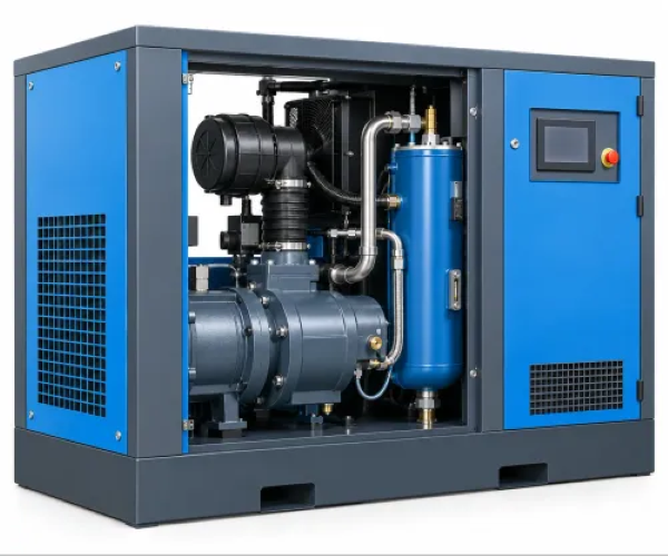
A rotary screw compressor produces airflow continuously as twin helical rotors turn inside a close-fitting housing. Air enters through the inlet port, fills the spaces between the rotor lobes and casing, and becomes trapped as the rotors mesh.
Moving along the rotors, each pocket becomes smaller, raising pressure until the compressed air reaches the discharge port.
The rotary screw compressor working principle avoids the start-stop strokes of a piston machine:
- A reciprocating compressor draws air through an inlet valve during the intake stroke.
- The piston reverses direction and reduces the cylinder volume during compression.
- It opens the discharge valve on the discharge stroke, creating pulsating airflow and pressure fluctuations.
A screw design earns its place when the plant has long daily running hours, frequent starts, stable base-load demand, and a high duty cycle. That makes it a suitable continuous duty compressor and a strong choice as a high duty cycle air compressor; a piston compressor remains practical for intermittent tools and long recovery periods.
Continuous-duty capability does not justify leaving a fixed-speed compressor unloaded. An unloaded machine can still consume roughly 15–35% of full-load power, so low demand needs control rather than idle running.
Use sequencing for multiple compressors, a receiver for short peaks and reduced cycling, and the correct control selection when demand falls below full output; a variable-speed machine can suit widely varying demand, but only within its efficient operating range.
Screw or Reciprocating: Match the Compressor to the Work
Choose a reciprocating compressor for a workshop where air tools run intermittently and recovery periods are long; choose a screw compressor for a steady base load, frequent starts, and long daily operation. This screw vs piston compressor comparison shows the trade-offs:
| Type | Duty and demand | Pressure, sound and airflow | Footprint, maintenance and cost |
|---|---|---|---|
| Reciprocating piston | Suits intermittent tools and long recovery periods; poor fit for continuous duty | Handles high pressure efficiently; louder, with strong pulsation requiring a receiver | Smaller initial purchase; needs valve, ring, belt and lubrication attention |
| Screw | Suits continuous duty, frequent starts and stable flow; prolonged unloading wastes energy | Usually quieter, with low pulsation; pressure capability suits most plant-air systems | Compact for sustained output; routine separator, filter, oil and cooler service; higher purchase cost |
A reciprocating compressor comparison should include its lower entry price, not just its motor size. A fixed-speed screw compressor can waste roughly 15–35% of full-load power while unloaded, so use sequencing or storage when demand falls.
VSD compressor energy savings have the strongest case when measured demand varies substantially. Minimum practical speed, inverter losses, oil-system behaviour, and higher equipment and controls cost reduce payback; size the machine from the demand profile, not the VSD label.
Oil-injected screws suit general manufacturing. Oil-free compression suits pharmaceuticals, food processing, electronics, and medical air when specified air quality demands it, but “oil-free” describes the compression chamber, not clean air throughout the system. Verify ISO 8573-1 filtration, drying, particles, water, and total-oil results.
Size the Compressor from Measured Demand, Not Connected Horsepower
Size the compressor from a short-term pressure and flow audit, not by adding pneumatic-equipment nameplates or motor horsepower. Record:
- Average, peak, and minimum flow during each shift
- Working pressure in bar(g), pressure band, allowable pressure swing, and peak duration
- Shift pattern, idle periods, control logic, and future expansion
- Receiver volume, altitude, and compressor-room inlet temperature
Compressed-air compressor sizing depends on free air delivery (FAD) in CFM or m³/min at a stated pressure. Compare that figure directly; compressor displacement versus FAD and motor horsepower can make an apparently large machine deliver too little usable air.
| Compare | Use | Avoid |
|---|---|---|
| FAD at stated bar(g) | Matches delivered capacity | Displacement alone |
| Measured peak and average flow | Matches real demand | Connected nameplates |
| Receiver tank sizing against peak duration | Covers short surges and reduces cycling | Treating storage as compressor capacity |
A receiver covers short peaks, but it cannot sustain a long demand that exceeds compressor capacity. Calculate pressure at the actual machine after pipe, fittings, valves, aftercooler, dryer, filters, hose, and coupler losses; increasing discharge pressure by about 1 bar can raise power use by roughly 7%.
SS Quality Air Solutions can turn these measurements into an equipment, receiver, piping, and control specification instead of sizing from horsepower alone.
Design the Air Network So Capacity Reaches the Machine
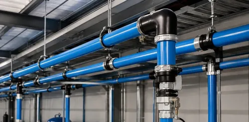
Use a ring main compressed air system instead of a dead-end header: air can reach each demand point from two directions, reducing and stabilising compressed air piping pressure drop. Branch drops should leave from the top of the header; drain legs belong at low points, because a bottom connection carries condensate toward the machine.
A large header does not guarantee flow. The bottleneck may be:
- A small hose
- A clogged filter
- A restrictive quick coupler
- An undersized branch
Install a wet receiver and dry receiver arrangement when the system design supports it: place the wet receiver upstream of the refrigerated dryer to separate bulk condensate and buffer compressor discharge fluctuations, then place the dry receiver downstream to supply treated-air peaks.
The arrangement depends on the system; all storage downstream can force short surges through the dryer.
With multiple compressors, run base-load machines near their efficient operating region and let one trim compressor follow short demand variations. Independent controls can make several compressors unload together while consuming power without producing useful air.
Choose the pressure dew point for the process. A refrigerated vs desiccant dryer comparison usually means about +3 °C for refrigerated drying and around −40 °C for desiccant drying. Desiccant systems consume purge air, so include that loss in compressor capacity and operating-cost calculations.
Protect Air Quality and Control the Lifetime Cost
“Oil-free” describes the compression chamber, not every point downstream. Oil-free compressor contamination can still come from intake air, ambient oil vapour, pipe scale, wear particles, and a dirty compressor room.
Specify ISO 8573-1 compressed air quality by separate particle, water, and total-oil classes. Do not treat “oil-free” as an air-quality class.
| Category | Specify | Check |
|---|---|---|
| Particles | ISO 8573-1 particle class | Particle size and concentration |
| Water | ISO 8573-1 water class | Pressure dew point and liquid water |
| Total oil | Class 1: no more than 0.01 mg/m³ | Include aerosol, liquid, and vapour oil |
| Total oil | Class 0 | Manufacturer-stated limits stricter than Class 1, with test conditions |
Oil-injected machines also create condensate at the separator, aftercooler, receiver, and dryers. Route it through approved compressed air condensate disposal equipment, such as an oil-water separator or sealed collection system; never discharge it by default to a floor drain or storm drain.
Treat compressed air leak detection as a capacity project. Use an ultrasonic survey because leaks disappear into factory noise, and poorly maintained plants can lose about 20–30% of compressor output. Maintain coolers and filters, replace clogged elements, verify control settings, and sequence multiple compressors so base-load machines operate efficiently while one trim machine follows demand.
Electricity usually outweighs the purchase price over the system life. A service plan, demand audit, and pressure verification can therefore save more than a small difference between quotations.
Frequently asked questions
How does a screw compressor produce continuous airflow?
Twin helical rotors trap air between their lobes and casing, compress it as the volume decreases, and discharge it continuously.
When should you choose a screw compressor instead of a reciprocating compressor?
Choose a screw compressor for steady, extended demand. Choose a reciprocating compressor when air use is intermittent and demand cycles allow recovery time.
What information is needed to size a screw air compressor?
Measure operating pressure, flow demand, duty cycle, peak consumption, leaks, and future demand. Do not size the compressor from connected horsepower alone.
How do you prevent pressure loss in a compressed-air network?
Use correctly sized piping, short routes, suitable fittings, isolation valves, receivers, filters, and dryers, then verify pressure at the point of use.